 Notch
NotchDIY Big Green Egg Table – Big Green Egg Table Project Plan
Step-by-step build — 47 steps. Also available as a print sheet.
1Cut the parts for the Base
- We will cut all the base frame parts first.
- Cut the legs from the 4x4s. You will need 6 at 30-1/2”.
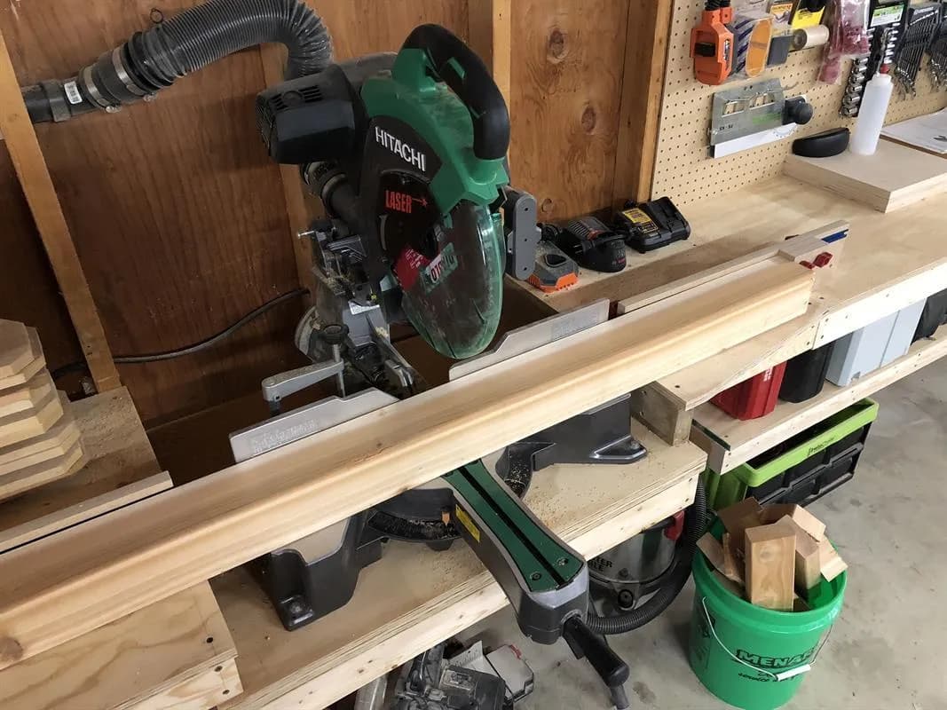
- Next, cut the 14 short rails from 2x4s at 18”. We will need 4 long rails, also from 2x4s, at 27-1/2”. These are all the parts needed for the frame of the base. I cut them at the miter saw.
- Trim one end first for a square cut, then use a stop block to make sure all subsequent cuts are equal. *Note: The parts list indicates actual dimensions of the 2x4 and 4x4 material; 1-1/2” x 3-1/2” and 3-1/2” x 3-1/2”, respectively.
2Cut the grooves in the Rails
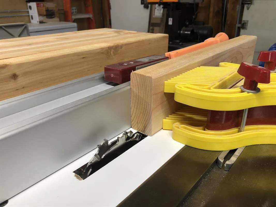
Next, we will cut the grooves in the rails that will house the floating panels. They are cut with a 1/2” dado stack at the table saw. You could also do this with a router. The depth of cut is set at 3/4”. A feather board is perfect for keeping the work tight to the fence. The grooves are cut in 2 of the long rails and 8 of the short rails. 1 additional short rail will get a groove on both edges. The remaining 5 short rails and 2 long rails do not get grooves.
3Drill Pocket Holes in the Rails
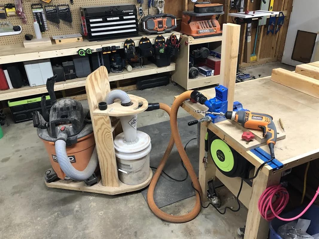
The Kreg HD is the perfect tool for the joinery on this project. It is designed for structural outdoor applications. These are seriously beefy screws! This jig is compatible with bench top Kreg bases like the K3, K4, and K5, or can be used on its own. Each rail will get two pocket holes on each end. Pick the best faces of each board to show outwards and drill the holes on the opposite side. Offset the holes towards one edge on the rails with grooves to avoid drilling into the groove space. Be extra careful with the rail that has two grooves. I like to use a corded drill and vacuum when drilling a lot of pocket holes. It helps keep the bit cool and prevents the jig from clogging up. Check out Link 5 in the Extras for more info.
4Route Grooves in Legs (Optional)
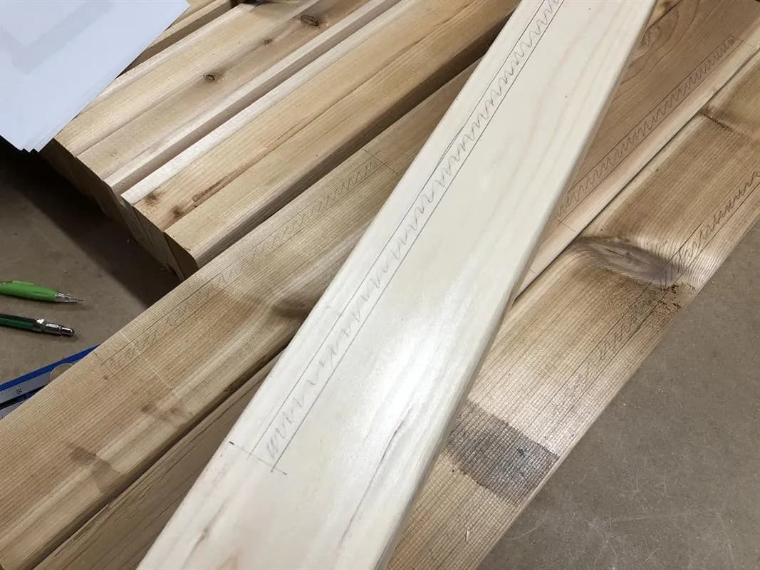
This is by far the most complicated step of this project, but it is also optional. Routing grooves in the legs to accept the floating panels will give extra room for expansion/contraction and also a cleaner look. Each leg gets a different set of grooves, so it is very important to pay attention when laying out and marking each leg. I will break this up into sections in the next several steps. Using a tool like the Kreg Multi-Mark ensures consistent layout. All of the grooves are inset from the edge by 5/8” and are routed to 3/4” deep. The length varies by the size of the panel. Refer to the Extras section for more detail. It is a good idea to mark the top and front of each leg and number them to avoid confusion as you go.
5Route Grooves in Legs - 2
Layout the grooves in the two right end legs. The front leg gets one groove on the back side to accept the side panel. The groove starts 4-1/4” from the bottom and ends 2-3/4 from the top. The right rear leg gets grooves on the front face and left face (as viewed from the front of the table). Both of these grooves also start 4-1/4” from the bottom and end 2-3/4” from the top.
6Route Grooves in Legs - 3
- Next, layout the grooves on the center two legs. The front leg gets two grooves on the back side to accept the center divider panels. The lower groove starts 4-1/4” from the bottom and is 10” long. The upper groove starts 2-3/4” from the top and is 11-1/2” long. They are marked 5/8” from the edge that faces towards the cabinet. The back center leg gets matching grooves on its front facing side. It also gets a groove on the right facing side that starts 4-1/4” from the bottom and ends 2-3/4” from the top to accept the large back panel.
- Finally, it gets a groove on the left facing side to accept the small back panel. This groove starts 4-1/4” from the bottom and is 10” long.
7Route Grooves in Legs - 4
Layout the grooves on the left two legs next. The front leg gets one groove on its rear face. It starts 4-1/4” from the bottom and is 10” long. It is marked 5/8” in from the outside edge. The left rear leg gets a groove on its front face to match. It also gets a groove on its right facing side to accept the small back panel. It is also marked 4-1/4” from the bottom and 10” long, and is marked 5/8” in from the rear edge. Again, please refer to the Extras section for 3D representations that make this much clearer.
8Route Grooves in Legs - 5
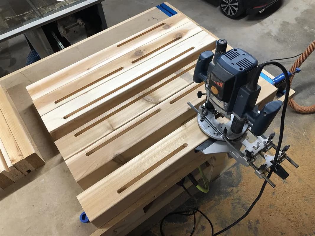
Okay, now that everything is marked out, we can go ahead and route the grooves. A plunge router with edge guide is the perfect tool for this task. It will ensure that all grooves are consistently spaced 5/8” from the appropriate edge and help to maintain nice straight grooves. A 1/2” diameter bit that can cut at least 3/4” deep is necessary. I like to make a full depth plunge at each end of the groove first and then make shallow passes connecting the two until I’ve reached full depth. Be sure to set your depth stop to 3/4” so you don’t go too deep. It is okay if you over run your start and stop marks by a little bit because it will be hidden by the rails, and will actually allow extra clearance for the corners of the floating panels.
9Prepare the Panel Boards
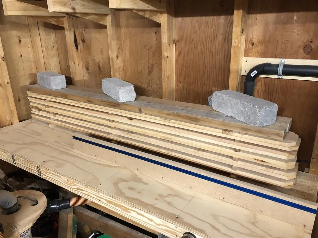
I use dog-eared fence pickets for the panel boards because they are readily available, affordable, and already close to the final thickness of 1/2”. Pick the flattest, straightest boards available. They tend to be quite wet from the store, so it is important to let them dry in your shop for a while. It is a good idea to stack and sticker them and keep some weight on top while they acclimate so they don’t warp like crazy. First I cut all of the individual boards I will need for all the base panels. The cut list indicates final dimension, but I cut them oversized by a couple inches and then trim them nice and square to final length after milling.
10Mill the Panel Boards
- Milling these fence boards to final dimension will allow them the fit in the groove, but it will also make for a nice seamless panel.
- First I joint one face and one edge of each board.
- Next, I trim them to final width at the table saw.
- Finally, they are brought to a final thickness of 1/2” with the planer. If you don’t have a jointer, you can find several tutorials for making a sled for your planer to do this job.
11Trim the Panel Boards
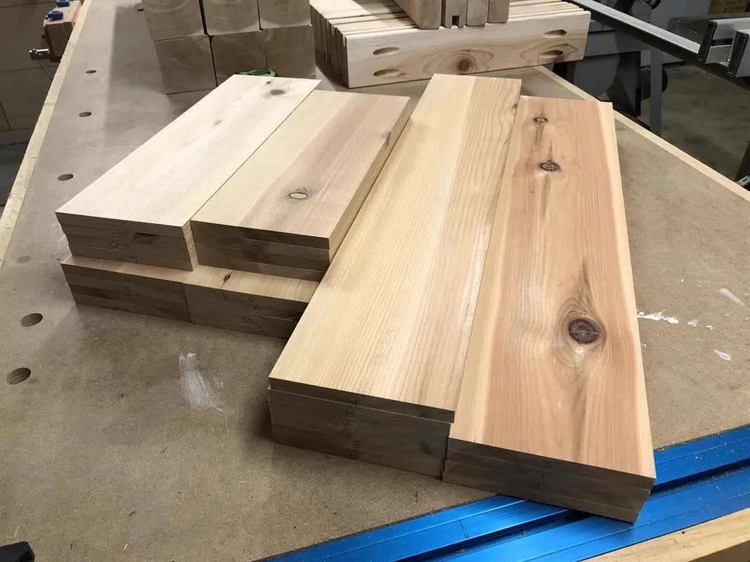
The Panel Boards, when put together, will be too wide for the panel opening. I trim the outer two panels so that the boards will fit in the opening with a little extra room for expansion and contraction. Trimming both outer boards ensures the panels remain symmetric in the opening.
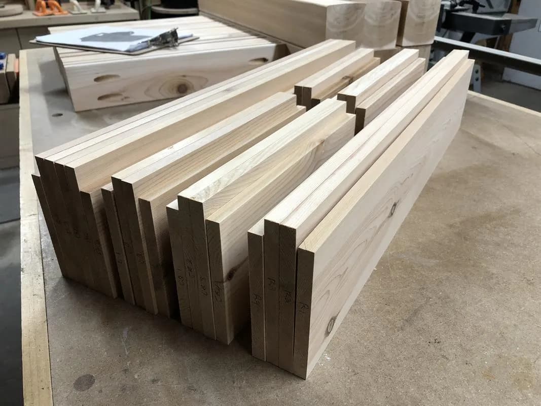
12Sand, Sand, Sand
Now is the time to sand all of the parts that make up the frame of the base. It is much easier to do this before assembly. The Ridgid Oscillating Spindle/Belt Sander is great for sanding the rails. I use an orbital sander for everything else.
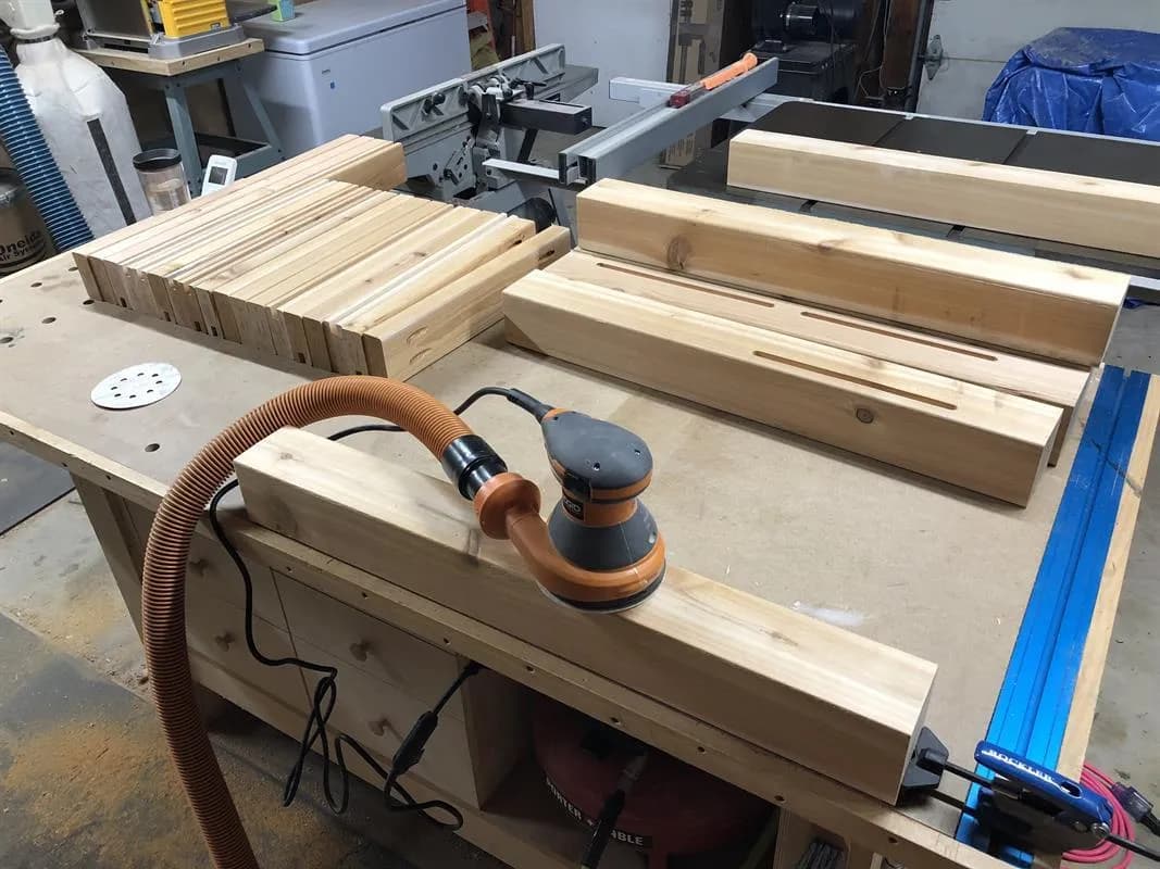
13Base Sub-Assemblies - 1
- The best way to assemble the base is in manageable sections. I start with the right end, center divider, and left end. The rails are set in from the face of the legs by 1/8”, so I use spacers to hold the rails 1/8” off the workbench.
- Mark the location of the bottom and center rails on each leg per the 3D sketches in the Extras section.
- Then I clamp up each section so it stays square while driving the screws. A rubber mallet can help make any fine adjustments to the alignment of the rails. I screw the rails into one leg only, then remove the clamps and add the panel boards.
- Then I re-clamp and add the screws on the other side.
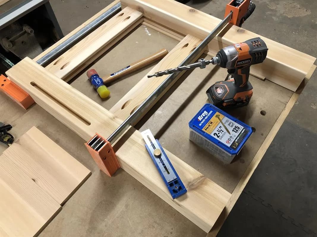
14Combine the Base Sub-Assemblies - 2
Go ahead and complete the base frame by combining the assembly from the last step and the right end sub-assembly with the long rails and panel. Clamps are your friend here. They really help keep everything tight and square and don’t let the rails wander when adding the screws. Now it’s starting to really look like something!
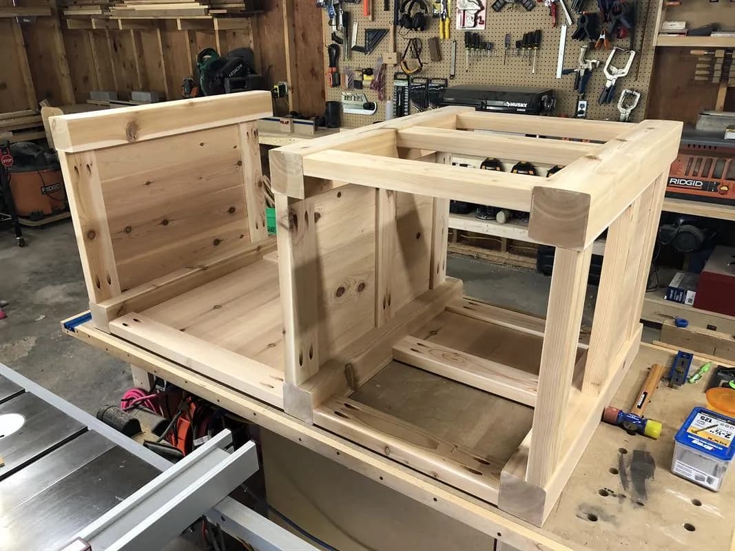
15Combine the Base Sub-Assemblies - 1
Using the same techniques from the last step, connect the left side assembly and center divider assembly with the front and back short rails per the diagrams. Be sure to check for square as you go. As long as your rail stock is straight and your cuts are square, there should be no surprises.
16Cut and Attach Cleats
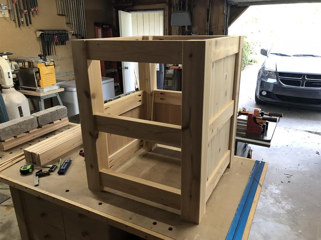
Cleats are use to support the cabinet floor boards and the grill platform boards. At the table saw, rip 1-1/2” x 1-1/2” cleats from 2x4s and cut them to length per the cut list. The two long cleats are mounted on the front and back long lower rails inside the cabinet, and a short cleat is mounted on the right side. The remaining short cleats are mounted on the middle front and back short rails to support the grill platform. All cleats are mounted 3/4” below the top of the rails so the floor boards will be flush with the top of the rails. Use the Kreg Multi-Mark to easily transfer this measurement. Clamp the cleats in place and then pre-drill and countersink for 2-1/2” deck screws every few inches.
17Cut and Attach Center Grill Support
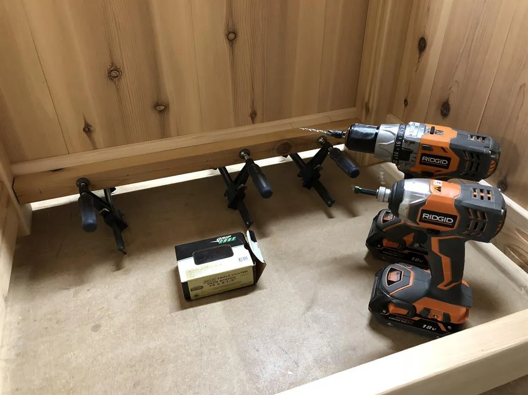
- The Big Green Egg is quite heavy, so a rigid center support for the platform is necessary.
- Rip a 1-1/2” x 2-3/4” board from a 2x4.
- Then take a measurement directly from the table where the support will go and cross cut the support to length. The length dimension in the cut list is approximate. It is always better to take dimensions directly from the work when you can. You want this to be a nice snug fit.
- Then drill two HD pocket holes on each end and screw it in place (3/4” below the top of the rails, just like the cleats). If it is a nice snug fit, it should be easy to get it aligned perfectly with help from a rubber mallet.
18Install Drawer Mounting Rail
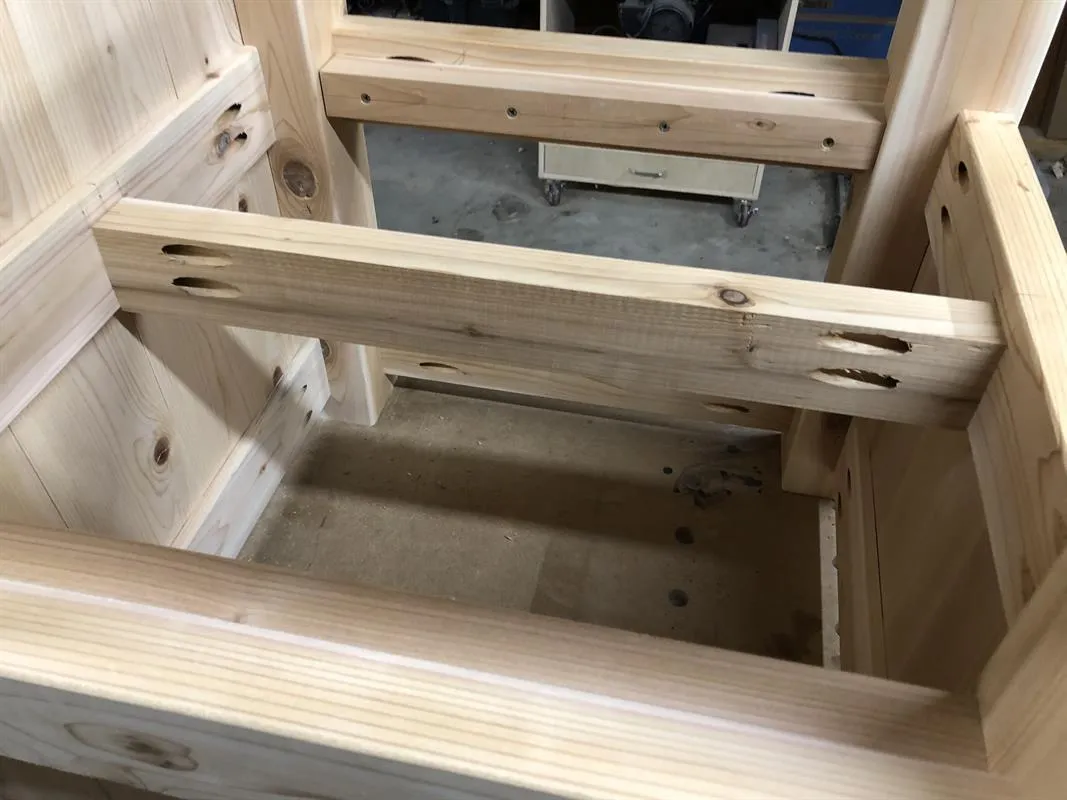
- This process works exactly like the last. A support is needed on both sides of the drawer cavity to mount the full extension slides.
- Measure and cut the rails from 2x4s to fit the opening and then drill and install with Kreg HD Screws. It is very important to make sure these rails are installed 90° to the front rail so the drawer is square in the opening and operates smoothly. If your cavity is square this won’t be a problem, but you may need to adjust these rails later if the drawer face isn’t flush in the opening. Mine needed a slight adjustment. I used a speed square hooked across the bottom front rail to make sure the mounting rail was perfect.
- Cut a few spacers to rest this rail on while screwing it in place to be sure it is level.
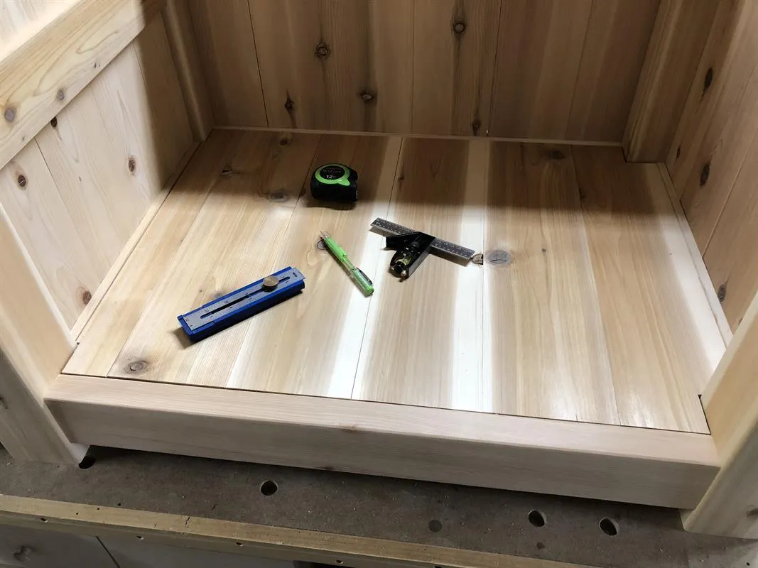
19Install Floor/Platform Boards
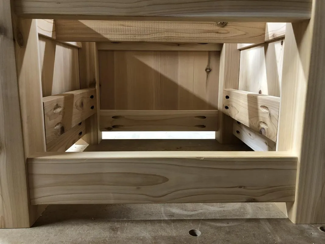
- The cabinet floor and grill platform boards are cut from 1x6 material. They are all cut to the same length.
- Take this measurement directly from the table, as the length dimension in the cut list is only an approximation. You will need 4 for the platform and 6 for the cabinet. The end boards will need to be ripped to width to fit. For the platform, I trimmed both outer boards for a nice symmetric appearance.
- Next, measure and notch out the corners of the end boards so they fit around the legs. I used a bandsaw, but a jigsaw will work just as well. These boards do not get permanently attached, allowing them to expand and contract. I also make sure they don’t fit too tightly for this reason.
20Build the Drawer Box
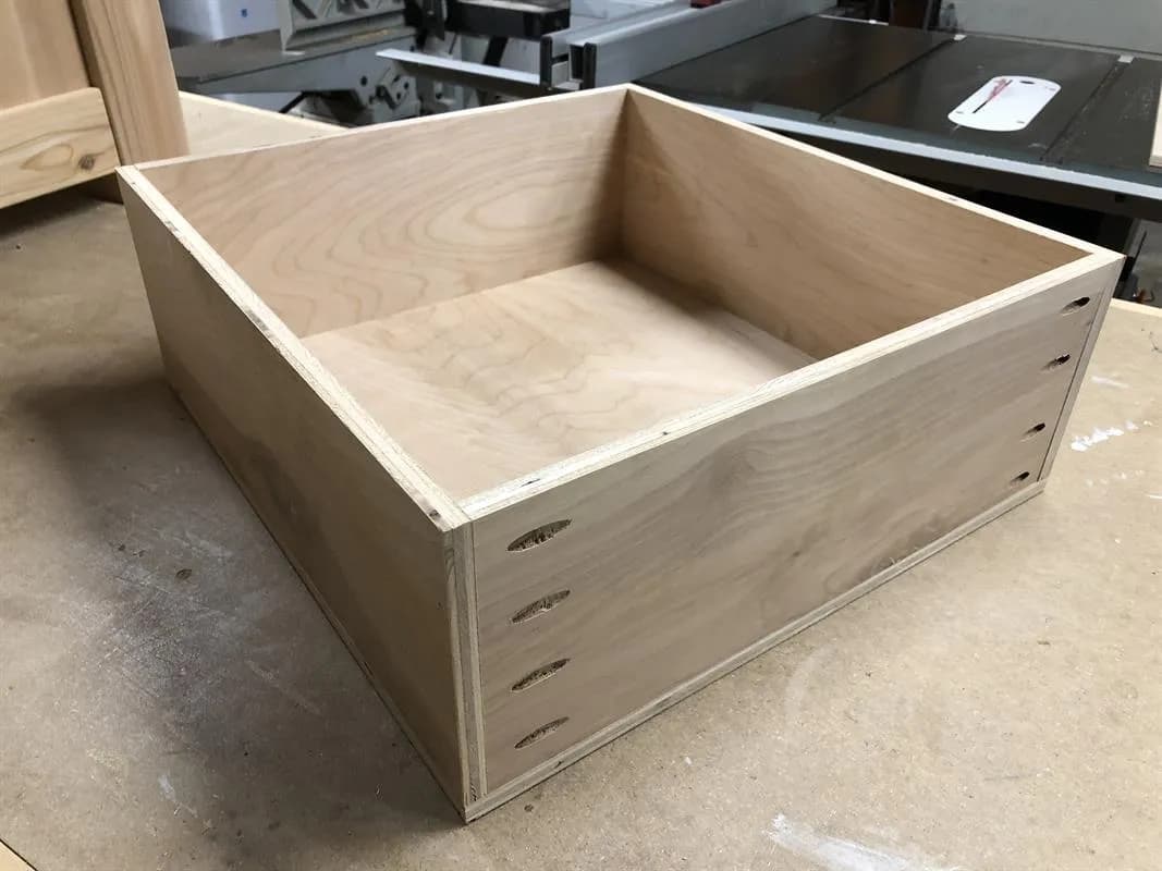
- From a 1/2” x 2’ x 4’ sheet of plywood, cut the drawer sides, front, back, and bottom to size per the cut list. On each end of the front and back boards, drill pocket holes. I prefer the Kreg Micro for 1/2” ply. It uses a much smaller bit and shorter 3/4” screws so they will not go through the material. It also fits into the bench top Kreg jigs, just like the KregHD.
- Next, attach the front/back to the sides with the pocket screws facing outwards. The pocket holes on the front will be covered by the false front and the ones on back will never be seen. Pre-drill and countersink #6 x 1” Wood Screws to attach the bottom to the sides. This is a very quick and solid method for making drawers.
- Check out Link 6 in Extras for more info.
21Prep Stock for Doors/Drawer Front
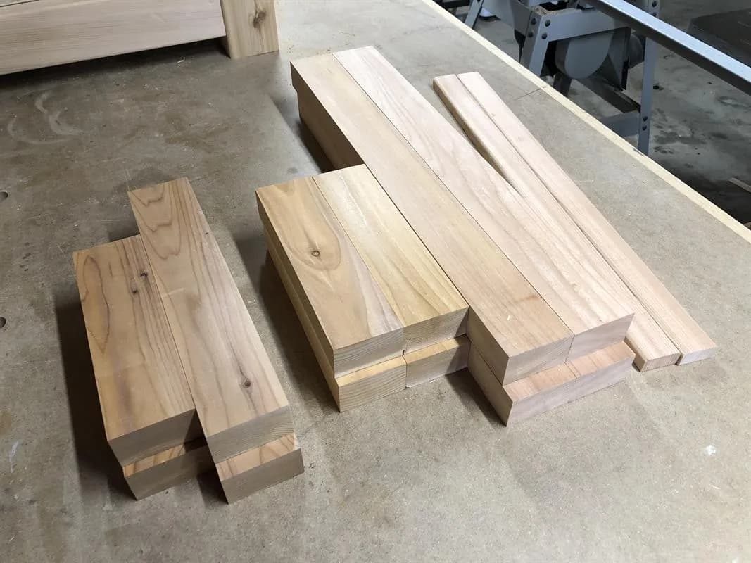
- The doors and drawer front are built using tongue and groove joinery with floating panels. The rails and stiles are made from 1-1/2” x 2-1/2” boards cut from 2x4s.
- Cut all of the boards to length per the cut list.
- Next, rip the rounded edge off one side of the board, then reset the fence for 2-1/2” and rip all the boards to final width. You will save two of the offcuts from the door stiles to be used as mounting strips later.
22Cut Grooves in Rails/Stiles
Next we will cut 1/2” wide by 3/4” deep grooves centered on the edge of all the rails and stiles. This is done at the table saw just as we did with the base rails earlier. However, this time I used a 1/4” dado stack and made two passes, flipping the board in between, to get a 1/2” groove that is perfectly centered. There are several great video tutorials available online that explain this method in great detail. (Link 3 in the Extras)
23Cut the Tongues on the Rails
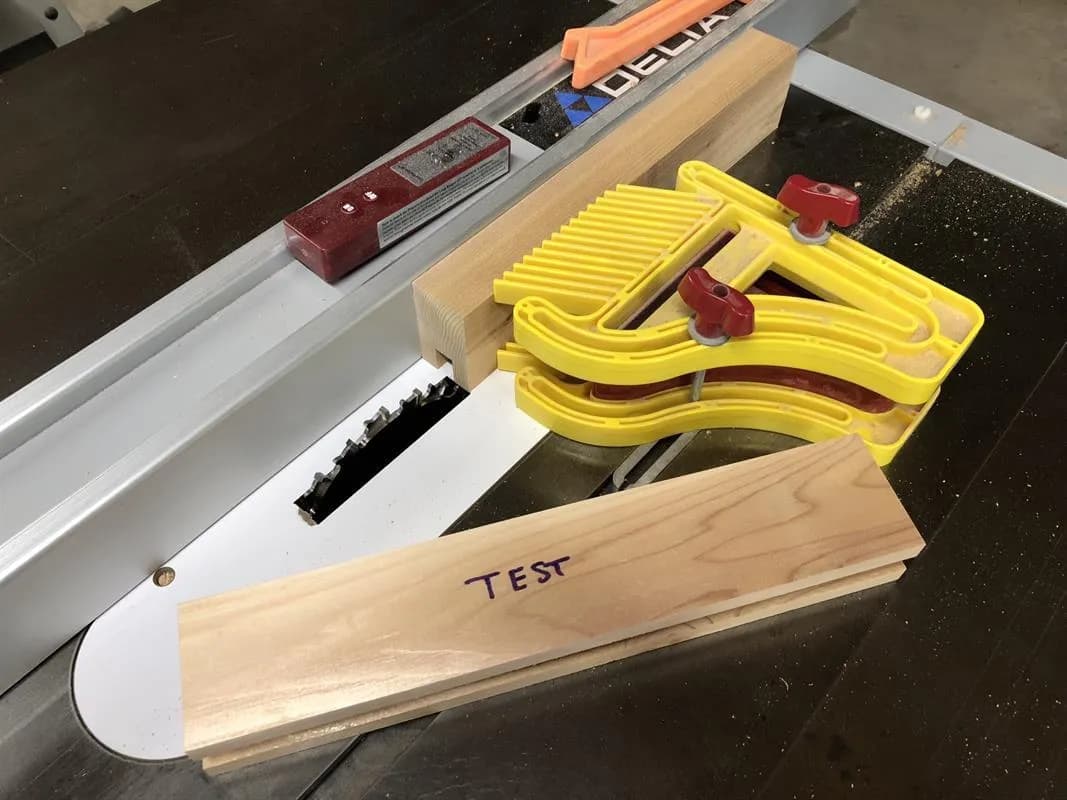
The rails are cut 1-1/2 too long to allow for the tongues that will seat in the grooves that we just cut in the stiles. The tongues are also cut at the table Saw with a 1/4” dado blade. The blade height is set even with the bottom of the groove with the rail on its side. The fence is set 3/4” from the left side of the blade. Using a miter gauge set to 90°, make several passes to clear out the waste then roll the board 180° and do the same on the other side. You will be left with a tongue that is 1/2” wide and 3/4” long. It should fit perfectly in the groove. Using a test piece allows you to dial in the table saw settings for a perfect fit. Repeat on the other end of the stile. Click Link 3 in the Extras section for a great video.
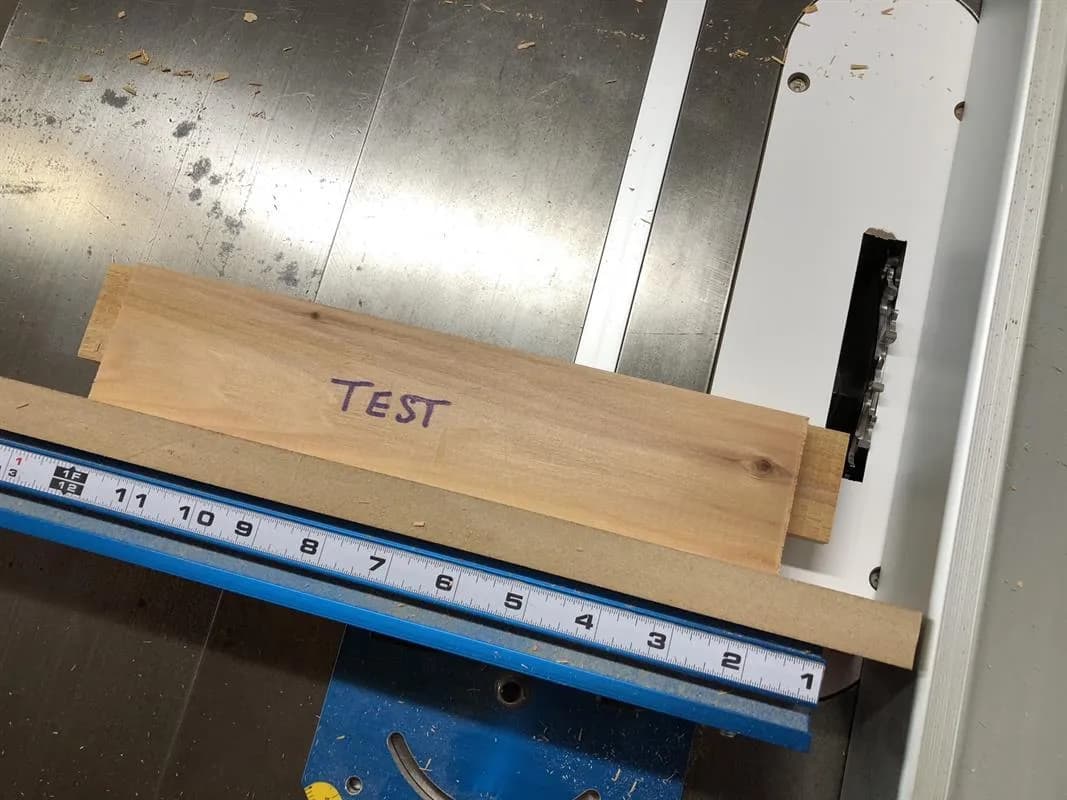
24Make the Panels for Doors/Drawer
- These panels are made the same as the base cabinet panels.
- Cut and mill the boards from pickets per the dimensions in the cut list. The door panel boards get glued together to make a solid panel. The cut list dimensions will result in panels that are too wide, so trim the finished panels to size, allowing a little room for expansion and contraction.
- Then do a final sanding on these panels before assembly.
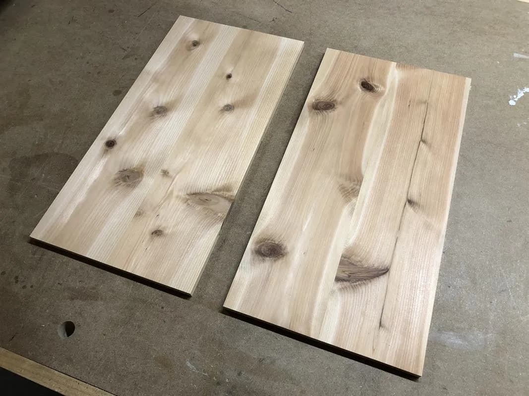
25Cut Mortises for Door Hinges
Layout the hinge mortises on the door mounting strips. The bottom of the lower hinge is marked at 3” from the bottom. The bottom of the top hinge is marked at 13-1/2” from the bottom. The hinges are 3-1/2 wide, so mark the width as well. Then transfer these dimensions to the outside stile of each door. The mortises are made at the table Saw with the dado stack. The blade height is set to match the thickness of one hinge leaf. Use a miter gauge to ensure square cuts. A zero clearance fence let’s you line up the kerf with marks on your work pieces. Sneak up on the marks using the hinge to test for a snug fit.
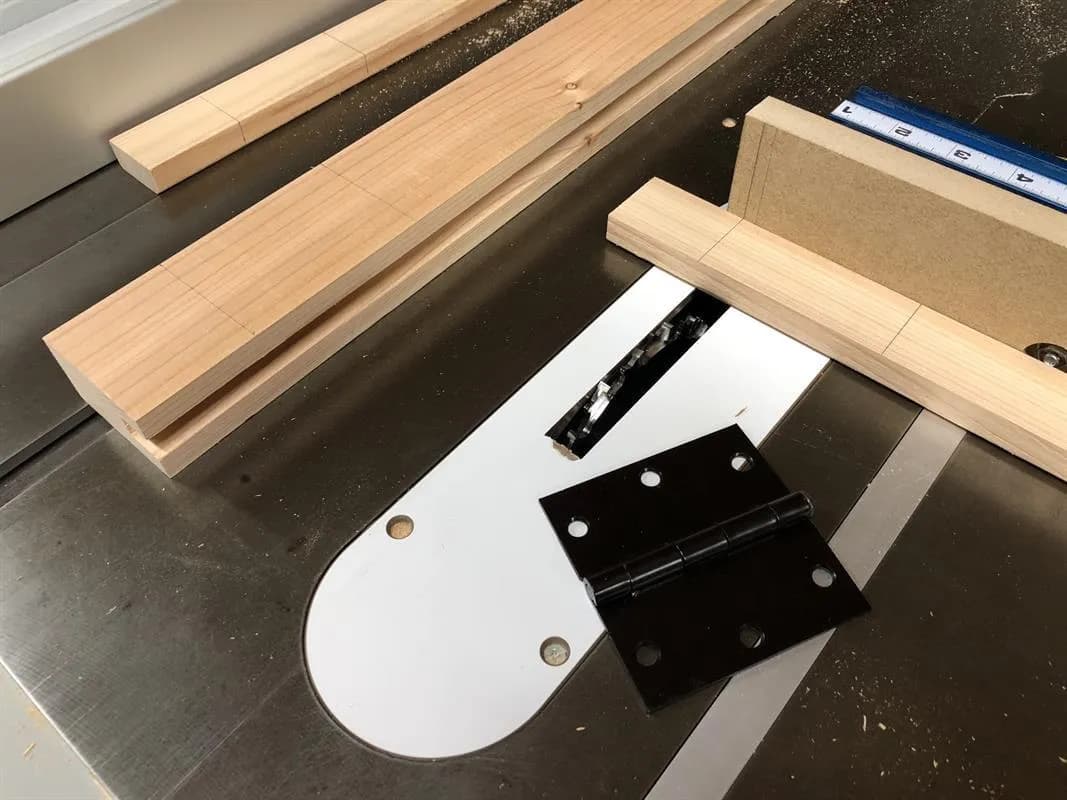
26Assemble the Doors/Drawer Front
- The doors and drawer front are now ready for assembly. All that is needed is wood glue. I chose Titebond 3 because it is formulated for exterior use and is water proof.
- Add glue to the tongue on one end of each rail.
- Then insert them into the groove on one stile.
- Next, insert the panel.
- Finally, add glue to the tongues on the other end of the rails and fit the last stile. One clamp across each joint is sufficient. These panels are meant to float because they are solid wood and need to be able to expand and contract. They are not to be glued in place.
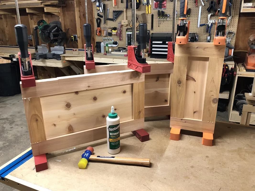
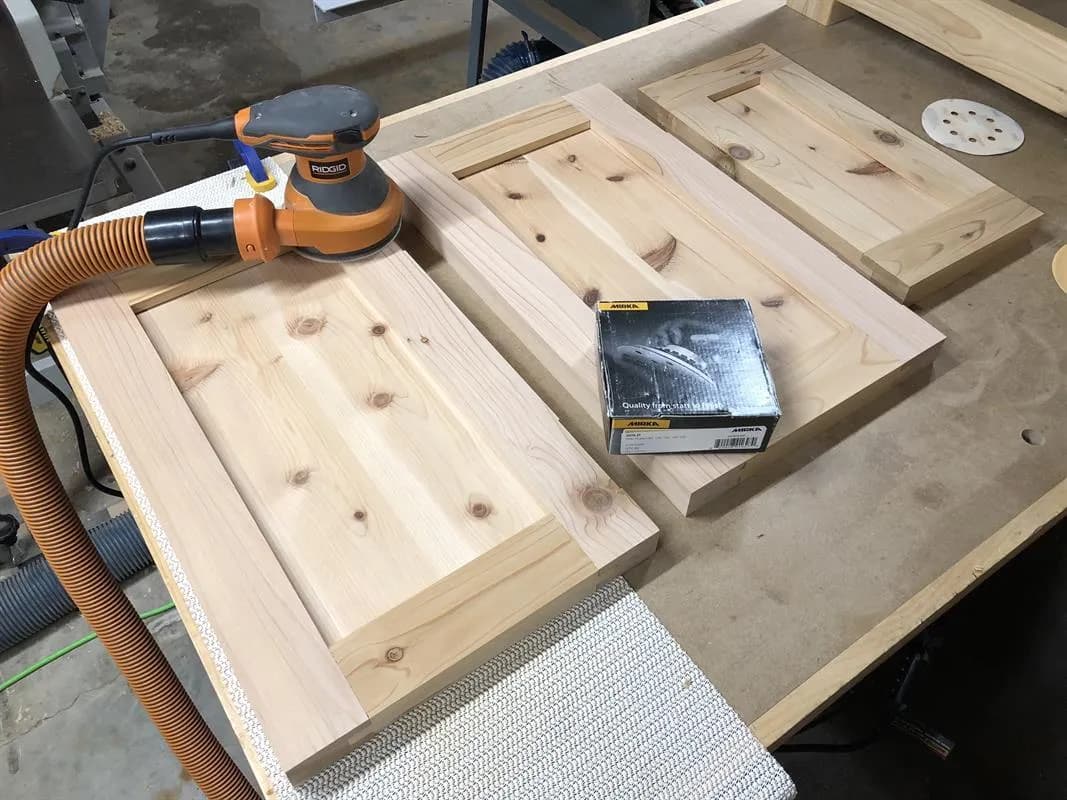
27Sand the Doors/Drawer Front
After the glue has set, remove the doors and drawer front from the clamps and do a final sanding.
28Install the Hinges
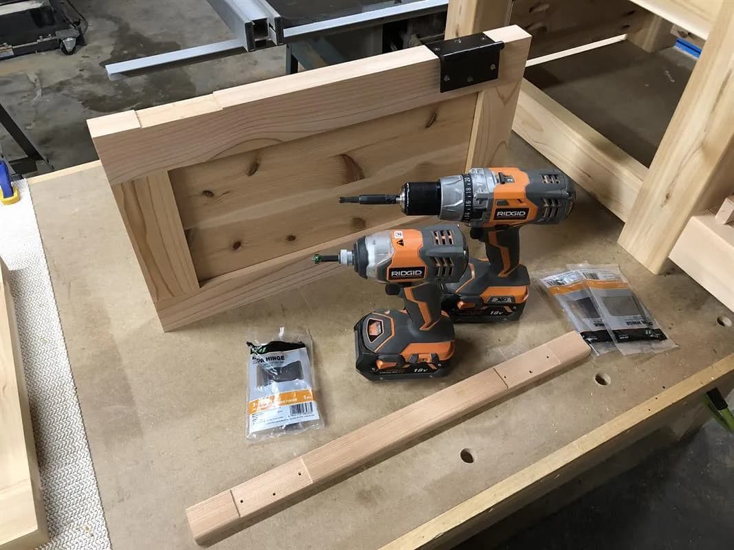
- Place the hinge in the mortise on the door stile. Use a vix style self-centering but to pre-drill for the hinges screws.
- Repeat for each hinge on both doors and both mounting strips.
- Attach the hinges to the doors and then to the strips. The doors should fit nicely in the opening.
29Install the Door Mounting Strips
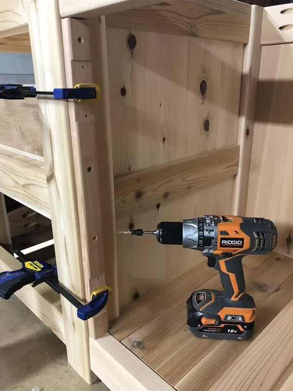
Pre-drill and countersink each mounting strip and then attach on either side of the cabinet opening with 1-1/4” deck screws. Be sure these are installed plumb to Cabinet front so the doors line up and close properly.
30Trim the Doors/Drawer Front
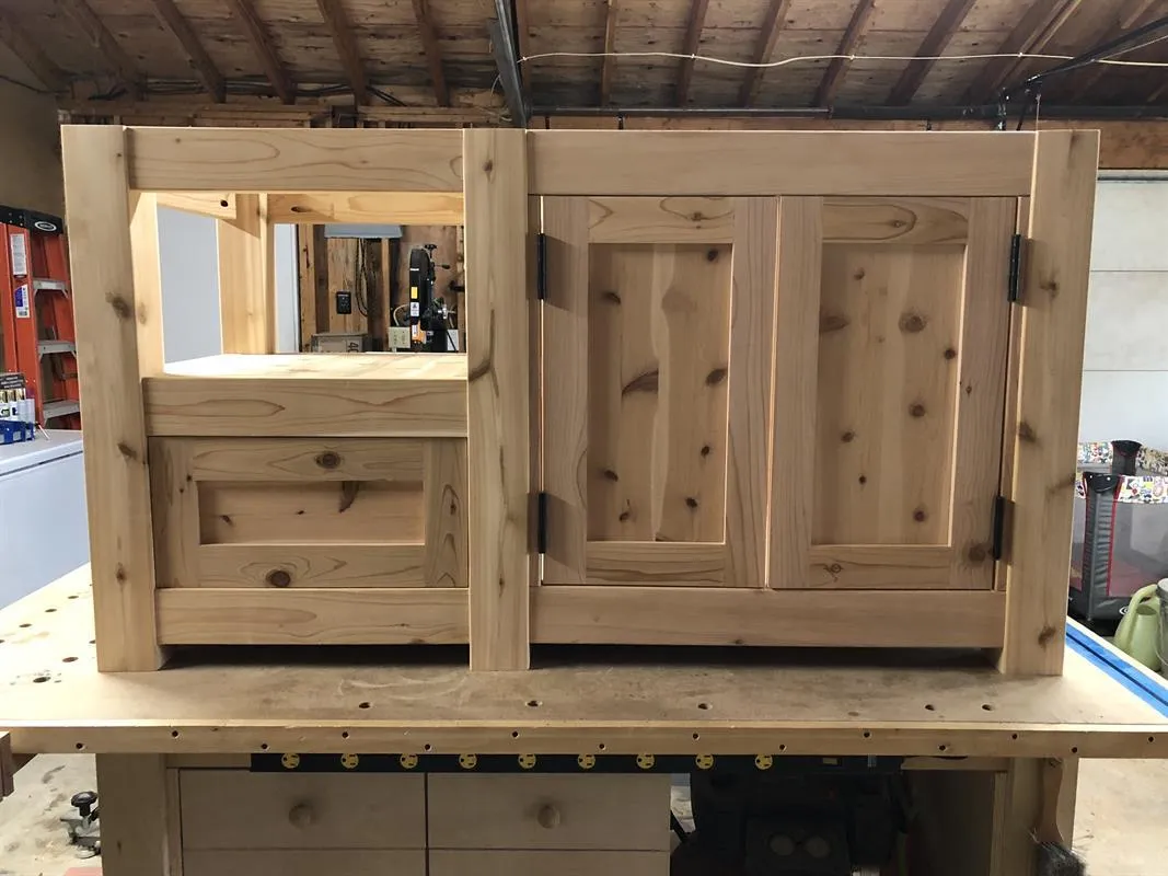
- The doors and drawer front will likely be too tight. At the table saw, trim a small amount from each side of the drawer front until it fits with a nice reveal.
- Next, trim a small amount from the top and bottom of each door until they fit well.
- Finally, trim the doors to width. Do NOT trim the jamb side because you will cut through the hinge mortises.
- Set the table saw blade to a 5° bevel and trim the inside edge of each door. If you have a right-tilt saw, the door front should face down, opposite for a left-tilt. The bevel is needed for the doors to clear each other when closing.
- Trim a small amount from each door until they close with an even reveal. You may have to install/uninstall the doors several times until they fit perfectly.
31Mount the Drawer Box
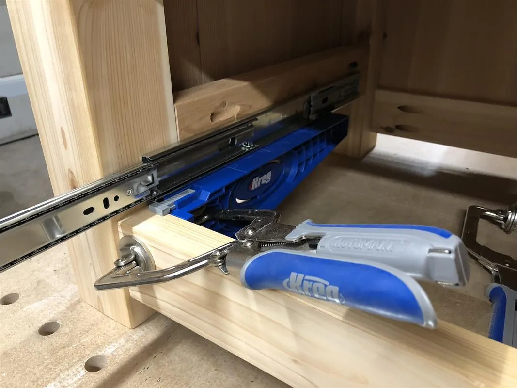
- Mount the drawer box using the Kreg Drawer Slide Jig. The front of the slide should be even with the back of the lower rail. This will allow the false drawer front to sit flush with the front of the rails.
- First mount the cabinet half of each slide.
- Then flip the jigs around and line up the drawer box portion with the front of the drawer box and install the first two screws on each side.
- Remove the drawer box and attach the last screw on each side. There are so many good tutorials on using this jig to install full extension slides.
- Check out Link 7 in the Extras for a helpful video.
32Install Door/Drawer Pulls
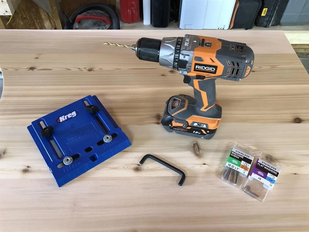
- I use the Kreg Cabinet Hardware Jig to install the pulls on the doors. This is a great jig with tons of adjustability. Because the doors are so thick, you will need longer mounting screws. I went with 8-32 x 2” Pan Head machine screws and #8 washers in stainless, as they will withstand exterior conditions.
- Next, install the drawer pull prior to mounting the drawer front to the drawer box.
- Mark out and pre-drill for the screws and then use 8-32 x 3/4” stainless machine screws and washers to attach the pull. We will install the drawer front in the next step.
- Check out Link 8 in the Extras for a video showing the Cabinet Hardware jig in action.
33Install Drawer Front
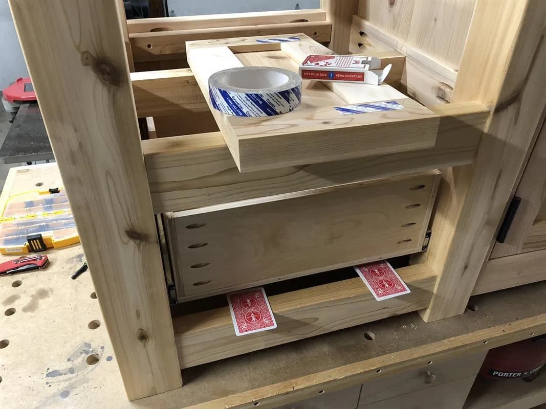
- A few tricks will help you install the drawer front easily with a nice even reveal.
- First, use playing cards to shim the drawer front until you have the desired reveal.
- Next, use two-sided tape to temporarily hold the drawer front in place until you can screw it on from behind. Readily available carpet tape works just fine.
- Then you can pull out the drawer with the face in place and permanently attach it with #8 x 1” washer head/cabinet screws from inside the drawer.
34Install Grill Tool Hooks
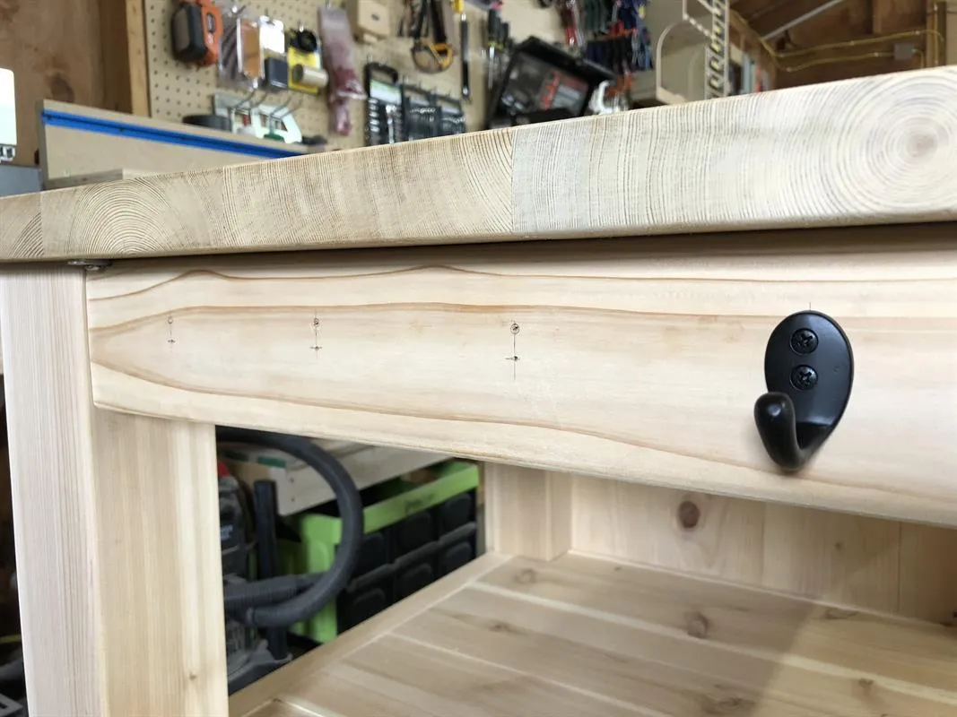
These hooks are a great way to store handled grill tools and keep them close at hand. Measure and mark out even spacing for the 4 hooks. Pre-drill for the mounting screws and then install the hooks. I find it easiest to install the screws with a screwdriver. The holes will easily strip it the screws are over-tightened with a drill or driver.
35Install Magnetic Door Catches
- Simple magnetic catches are perfect for keeping the doors latched securely in place and can be found in many finishes to match the rest of the hardware you choose. All of the hardware on this table is an oil-rubbed bronze finish. To install, hold the catch on the cabinet floor so it Butts up against the back of the door when it is fully closed.
- Mark for screw holes, pre-drill, and attach the catches.
- Then mark the hole location in the catch plate on the back of the door while it is still attached to the magnet.
- Mark, pre-drill, and attach the catch plate to the door.
36Mill the boards for the Top
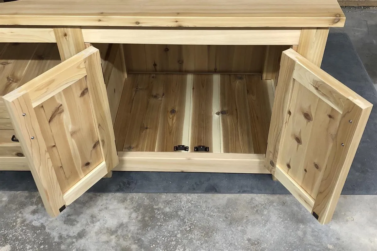
For my build, I used rough sawn cedar boards and milled them to final dimension. They went through the jointer, table saw, and planer until I had flat boards with parallel opposing faces. You can just as easily use dimensional boards as indicated in the materials and cut lists. If you use dimensional boards, pick the straightest boards you can find. Then rip the rounded edges from both sides so you have nice square edges. The finished size of the top is 58”L by 27”W. It is a good idea to make it a bit bigger in each direction and trim it to final size after glue-up. Spend a little time picking the nicest faces and best orientation of the boards to get a look you like. Do a test run with a clamp to make sure the seams will close completely.
37Glue-up the Top
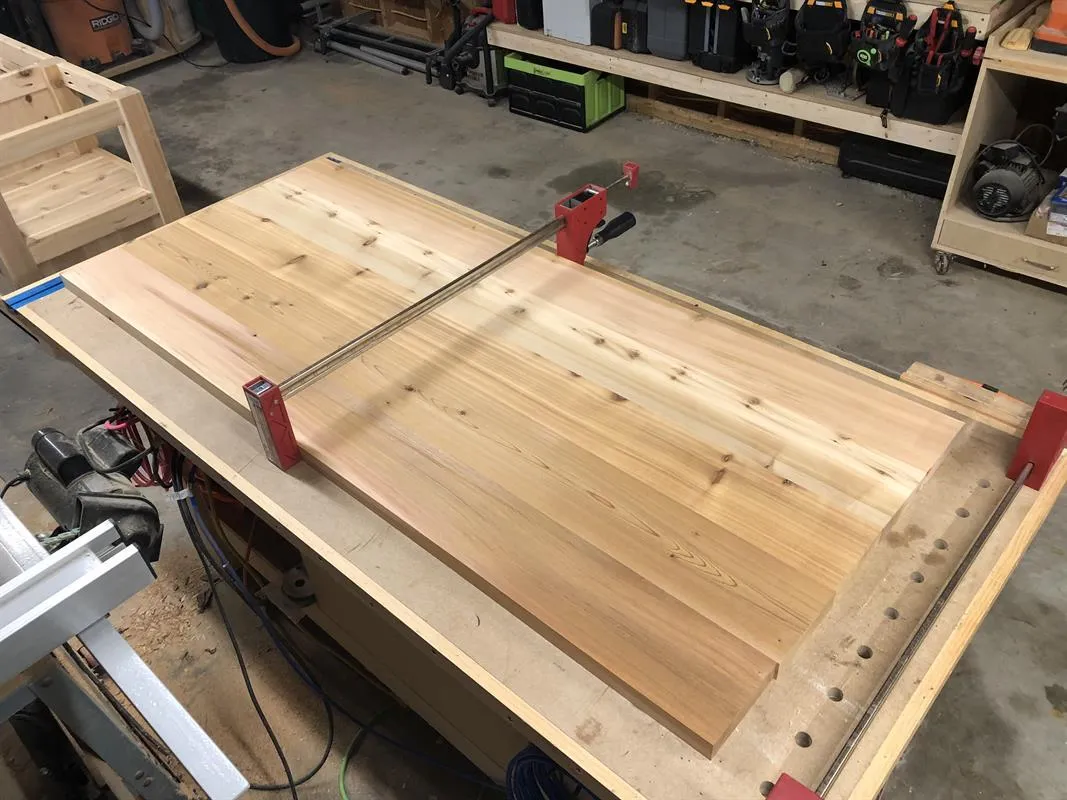
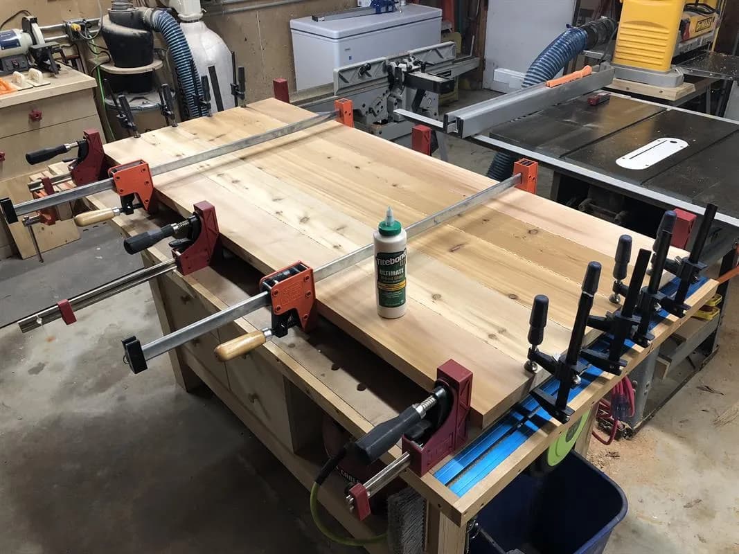
If your boards are milled properly and the joints close completely, there is no need for anything but glue to join the top. If it helps, you can use biscuits, dowels, or even dominos to keep the boards aligned and the top flat. Again, use Titebond 3 for its waterproof qualities and be sure to use sufficient glue. You should see a nice consistent line of squeeze out at each seam the whole length of the top. A clamp every foot is a good rule of thumb for panel glue-ups, and alteraniting which side of the top the clamp is on will help prevent cupping. I also like to use an f-clamp on each seam at each end to help with alignment.
38Trim the Top to Final Size
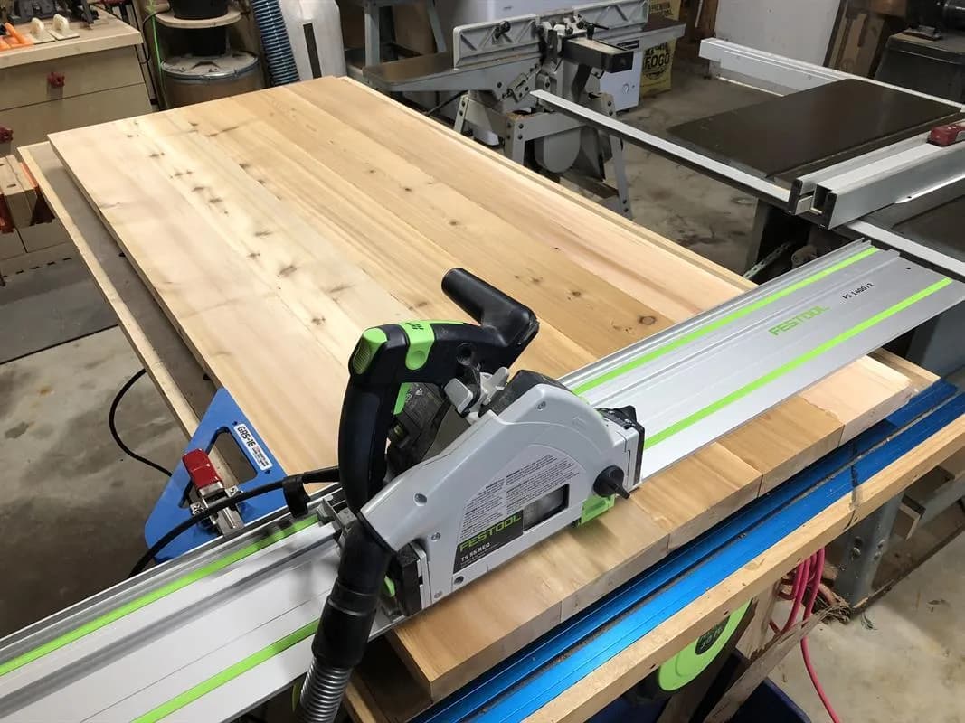
- After the top comes out of the clamps, trim it to final size with a circular saw or track saw.
- Start by crosscutting one end, then mark the final length of 58” and crosscut the other end.
- Then do the same for the width, ripping it to 27”.
39Sand the Top
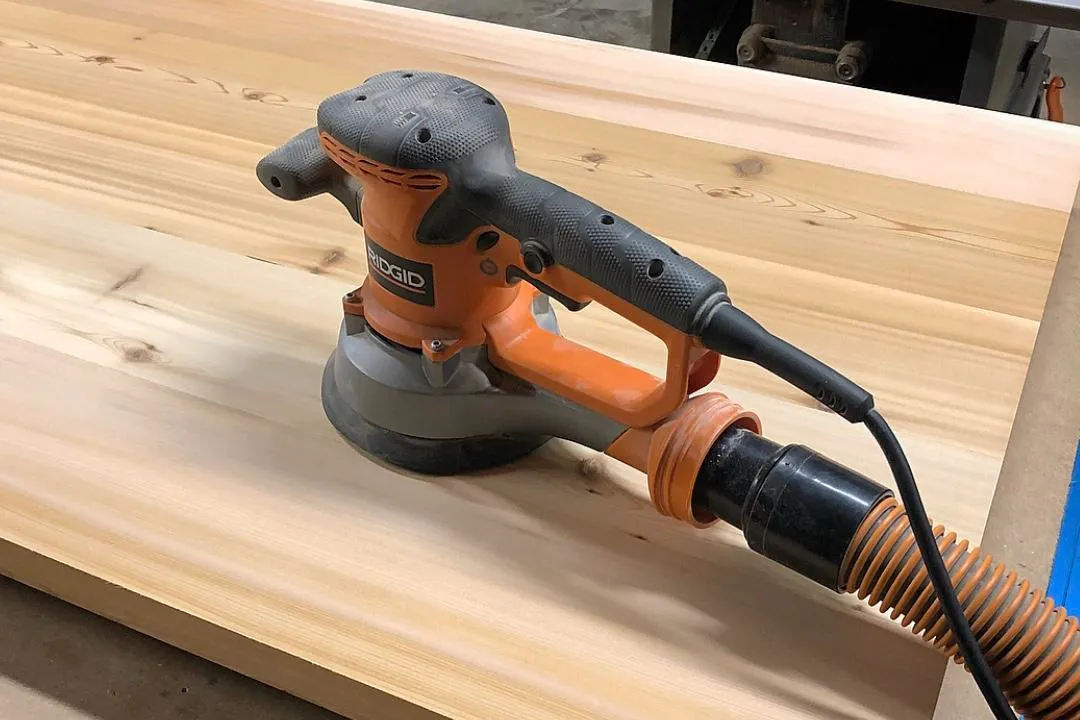
Nothing complicated here. This is the part of the table that will be seen the most, so take care to sand well and don’t skip any grits. A larger 6” orbital sander is great for large panels like this. I sanded up to 180 grit. Then I hand sand the edges with a nice firm sanding block.
40Cut the Hole - 1
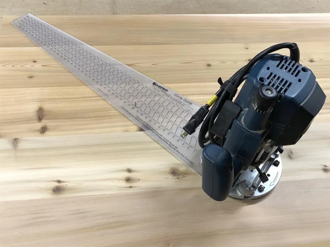
- The hole for the BGE is 21” in diameter. Because the Top is nearly 1-1/2” thick, it is best to cut this hole in a series of steps for the cleanest possible results.
- First, layout the center of the hole (13-1/2” from the left edge and 13-1/2” from the front).
- Next, use a plunge router and circle jig to route a circular groove that is 21” wide to the outside. A homemade jig works just as well as commercially available models. Make several cuts, going progressively deeper with each pass, to reduce strain on the bit. My bit has a cutting length of 1-1/4”, so there is about an 1/8” of an inch still connecting the disc to the hole. The next step will show removing the center disc.
41Cut the Hole - 2
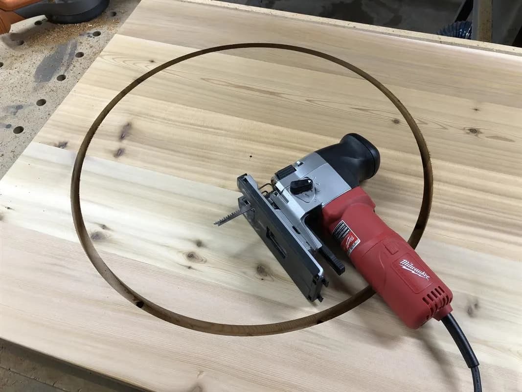
After routing the circular groove as deep as your bit will allow, the next step is to use a jigsaw to cut the rest of the way through. Start by drilling several clearance holes around the groove with a 3/8” drill bit. This will allow for a place to stop and start the cuts. Follow around the circle with the jigsaw, keeping the cut inside the groove. This will release the disc from the hole. The next step will clean up the jigsaw cut.
42Cut the Hole - 3
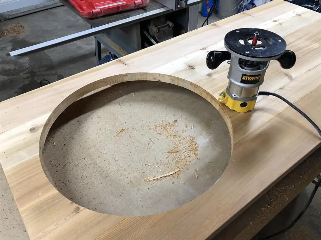
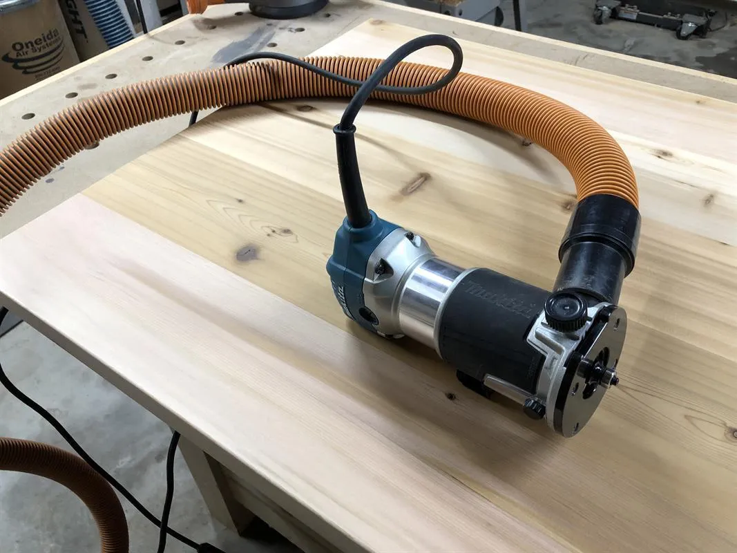
To finish the hole and leave a nice clean edge, use a flush trim bit in the router. Flip the top over and run the bearing along the inside of the hole where the initial router passes were made. This will clean up the jagged cut left by the jigsaw. You will be left with a perfectly circular hole with straight walls.
43Finish the Top
All that’s left to finish the top is to run a roundover bit around all the edges, including the inside of the circle. This will break the shar edge and give it a nice finished look. I prefer a very slight roundover, so I use a 1/8” Bit. This is enough to clean up the edge but leave it looking clean and not over-done. Don’t forget to do the underside of the top as well.
44Attach the Top - Background
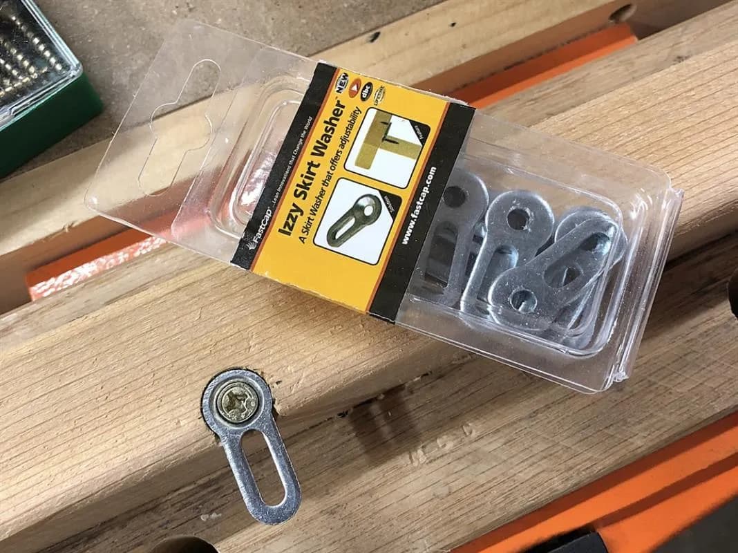
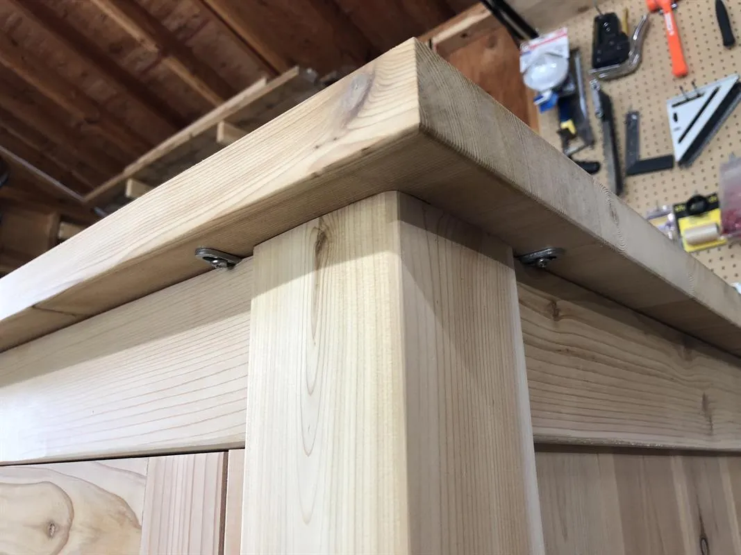
When using solid wood, it is always important to consider how the material will move as it expands and contracts and allow for that movement wherever possible. You may be tempted to just screw it to the base, but that would be ill-advised. The top will tend to expand or contract along its width, so we need to find a way to attach it and keep it flat while allowing it to move so it doesn’t crack or split. My preferred method is the Izzy Skirt Washer from FastCap. The circular hole is mounted to the base. A screw then goes through the elongated hole into the underside of the top. This allows the top to move laterally but remain flat. The next step will outline the process for installing the the fasteners.
45Attach the Top - Install Fasteners
- Izzy Swan has a great YouTube video demonstrating these fasteners. There will be a link in the Extras section for reference (Link 4).
- First, layout the locations for each fastener. They are installed in the top of the rails; one inch from either side of each corner leg and another on the long rails near the the center leg. They are marked 1” from the leg.
- Next, drill a 9/16” countersink 1/8” deep with a forstner bit.
- Attach the fasteners to the rails with a #8 x 1” screw.
- Then center the top on the cabinet.
- Place a mark on the underside of the top at the center of each elongated slot.
- Next, turn over the top and pre-drill the holes. Replace the top and attach it with #8 x 3/4” stainless pan head screws.
46Applying the Finish
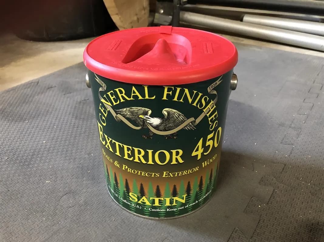
Now that the table is completely assembled, let’s take it back apart and apply the finish. I chose General Finishes Exterior 450 Satin for this project. It is water based and formulated for exterior use. It is fortified with UV absorbers and contains a mildewcide. There is a link in Extras with more information about this finish (Link 10). It sprays easily with an HVLP and I was able to apply all 3 coats in one day. Reassemble the table, add a Nest and your Egg and the project is complete. Let’s fire up the grill! *Note: Table is designed for use with a Table Nest (Link 9), or two 12” x 12” landscaping pavers to protect the wood. Link 2 is for a very nice protective cover that has kept my table looking brand new after more than a year.
47Base Sub-Assemblies - 2
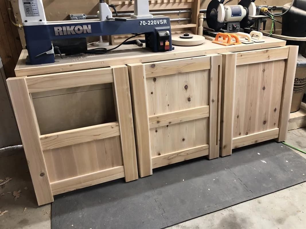
When you are done building the three separate sub-assemblies, you should be left with something looking like this. Next, we will connect these assemblies with the front and back rails to complete the base frame.